GrowBot · Body Build
Give the creature a body: two servo legs, a phone for a brain. No terminal, no coding, no prior hardware needed.
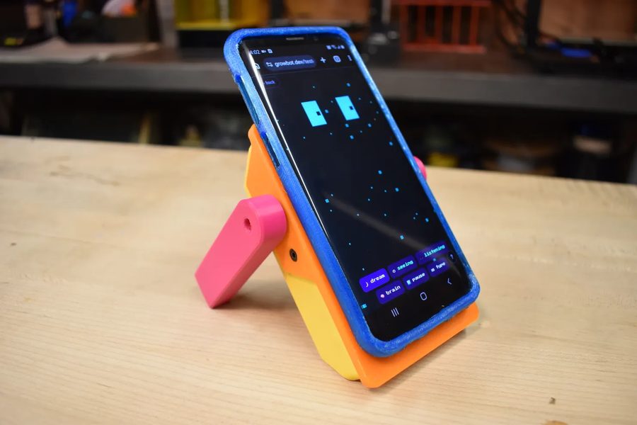
00Will this work for you?
Before you start, let's confirm your phone is supported. You do not need a SIM, just Wi-Fi. Load this page on the phone you plan to use and look for a green dot below.
Trouble with this step?
The check page fails on my phone. Try a different browser on the same phone first. If it still fails, use a different phone for the first build. The phone side is hard to work around later.
01Get the parts
Order these first to get started
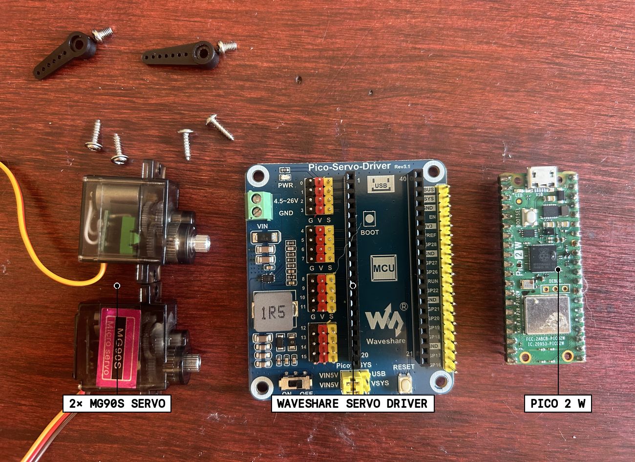
- Raspberry Pi Pico 2 W ↗ with header pins, ×1 · ≈ $7
- Waveshare Pico Servo Driver (the carrier board) · ≈ $10-25 · get whatever's cheapest for you: direct from Waveshare ↗ or on Amazon ↗
want to use another board?
The Kitronik Robotics Board (5329) is also tested and works. A couple of steps differ (socket numbers, minimum voltage), and this guide's photos show the Waveshare. The Kitronik Simply Robotics (5348) works too, with one edit: it has no servo chip and wires its sockets to different pins, so openPicoRobotics.pyand setGPIO_PINS = {1: 15, 3: 13}(sockets 0 and 2). Two builders found that independently, thank you. Using an ESP32 instead of a Pico? That's a supported path with different (command-line) flashing steps: see the ESP32 build guide. Anything else: ask in Discord. - 2× MG90S micro servos ↗ (metal-gear, horns + screws come in the bag; fit is brand-sensitive, this Miuzei pair is field-confirmed to seat correctly) · ≈ $17 / pair
And these you can find or source locally
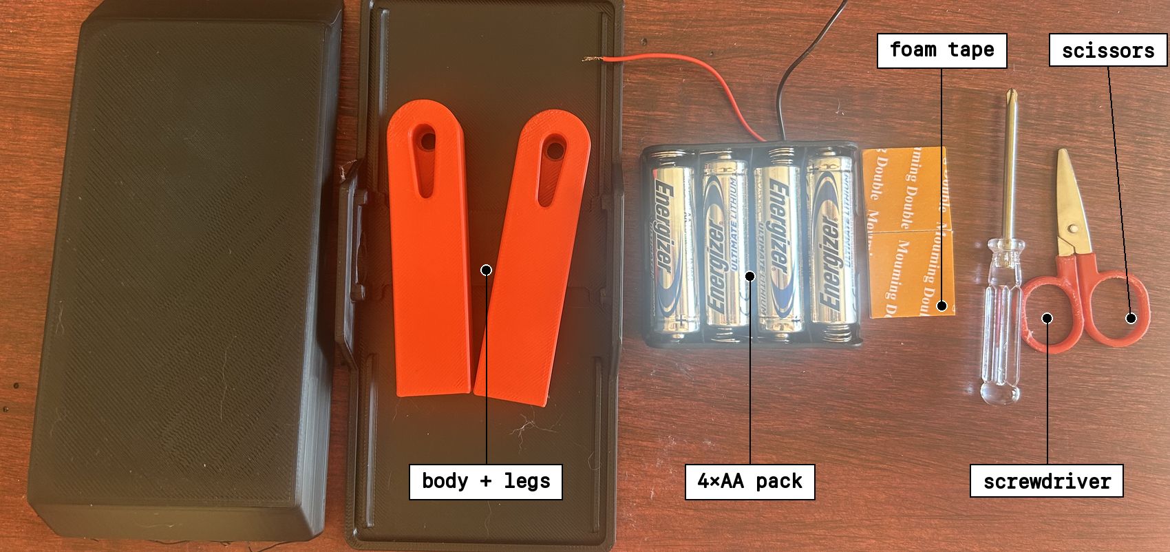
- Body + legs: ↓ STL files (plain PLA) · No printer? cut-from-anything template ↗
order the body printed instead?
No printer and no interest in the cutout version? order the body printed and shipped to you ↗ (~$15, print-on-demand). - Power: 4× AA lithium batteries (the single-use or rechargeable kind, either works) · rechargeable option on Amazon ↗
- Battery Holder: a low-profile 4×AA holder with bare wire leads (skip the ones with a cover or switch, they are bigger and won't fit the body) · on Amazon ↗
want to use other power?
Almost any small 5 V supply works (a 4×AA pack, a USB power bank on 5 V, a 1S LiPo + boost board). The floor depends on your board: the Waveshare needs at least 4.5 V, the Kitronik runs down to 3.7 V. Whatever you use must deliver a steady ≥ 2 A, servos spike when they move. - Two-sided foam tape (holds the phone + battery on)
- A small Phillips screwdriver (for the leg screws, servos just push into their slots)
- A tiny flat-head screwdriver (for the battery wires' screw terminal on the board; a small pair of scissors works too)
Trouble with this step?
Can I use SG90 servos instead? They will move, but the plastic gears strip once it starts walking. Get the MG90S.
My Pico has no header pins. This guide assumes pins already soldered on. A bare Pico needs soldering first.
I have a different carrier board. It may well work, the firmware auto-detects most PCA9685 boards, but this guide photographs the Waveshare. Check the optional boards list or ask in Discord.
02Wake the board
Before building anything, let's confirm your hardware works. This is the only step you need a computer for. When it's done, the Pico board has a name and is on your Wi-Fi.
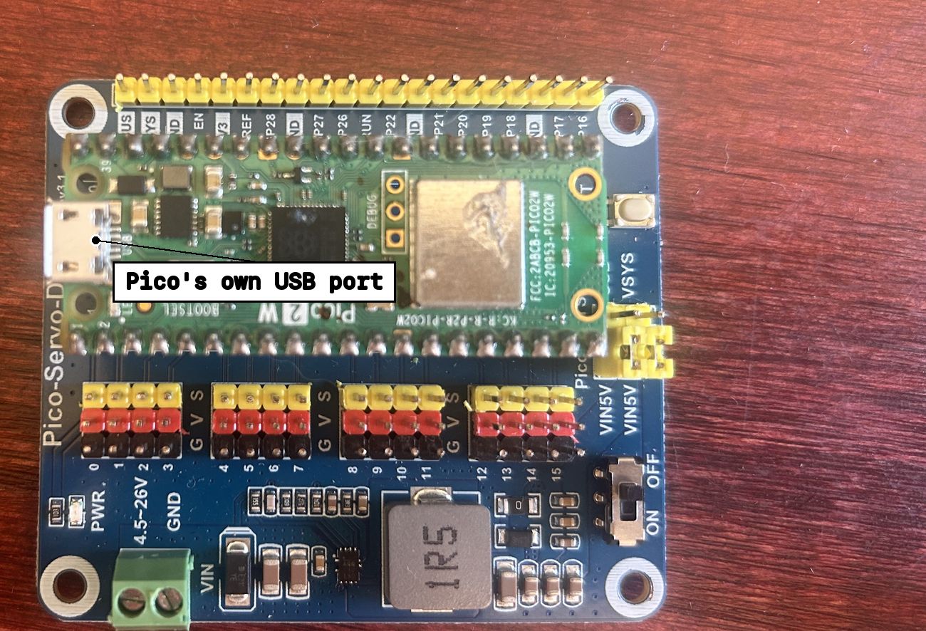
2A · Seat the Pico on the carrier board and leave it there
The Pico stays on the carrier board for everything, including flashing. Push it into the socket with the USB connector facing the end the board marks for USB.
2B · Put MicroPython on it
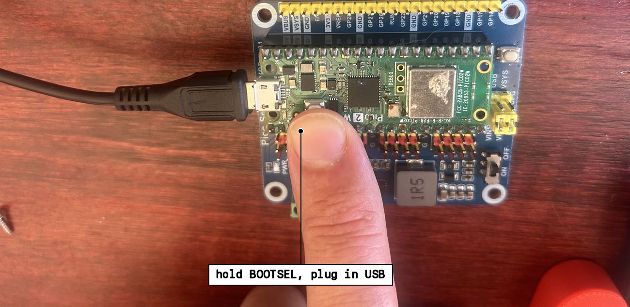
- Hold the Pico's white BOOTSEL button.
- Still holding it, plug the USB cable into the Pico's own port and your computer. Let go.
- A drive called
RP2350appears on your computer. No drive is normal if you forgot to hold BOOTSEL, unplug and try again. - Download the MicroPython runtime (.uf2), then drag that file onto the
RP2350drive. - The drive vanishes by itself. That is success, not a crash. The Pico is no longer a drive from here on.
2C · Add GrowBot's code and your Wi-Fi
This part needs a computer, not the phone. The installer talks to the Pico through its USB cable, and only desktop Chrome or Edge can do that. Safari and Firefox can't (they don't support it), and phones can't either. On the right setup, use the one-click installer. Anything else: the Thonny path below works everywhere.
Easiest In your browser, one click desktop Chrome / Edge
Optional · advanced By hand, with Thonny
Most people can skip this. It is the manual path for when the one-click installer isn't an option, or you want to see the files. Thonny is a free editor for MicroPython boards: thonny.org.
Connect: Run > Configure interpreter > MicroPython (Raspberry Pi Pico), port = the Pico's serial port (usbmodem… / COM…, or auto-detect). The Shell shows a MicroPython prompt when it's talking.
Copy 4 files from the kit download, each one: File > Open (This computer) then File > Save As (Raspberry Pi Pico):
PicoRobotics.py→ save asPicoRobotics.pyact_engine.py→ save asact_engine.pysecrets.example.py→ type your Wi-Fi name + password into it, save assecrets.pyrelay_chip.py→ save asmain.py(the name matters, MicroPython auto-runs main.py at boot)
Unplug, replug, and watch Thonny's Shell for PAIRING CODE: gb-…
- the installer shows a pairing code like
gb-a3f9c1 - write it down now, it is this robot's name forever:
Trouble with this step?
No serial port / COM port shows up. A blank Pico never shows one, that's normal. The serial port only exists after MicroPython is installed (2B). Before that you should see the RP2350 drive instead, with BOOTSEL held.
No RP2350 drive either. The cable is power-only, or it's not in the Pico's own USB port. Swap cable, use the Pico's port, hold BOOTSEL while plugging in.
The Pico still shows up as a drive after flashing. Replug without holding BOOTSEL. If the drive returns, the .uf2 didn't take, drag it on again.
The browser installer can't see anything. Web Serial is desktop Chrome and Edge only. Not Safari, not Firefox, not phones or iPads. Use the Thonny path instead.
No pairing code appears. Open Thonny and restart the Pico, any error prints in the Shell. The most common: Wi-Fi name or password typo, or a 5 GHz-only network.
03Say hello from your phone
Before any building: prove your phone can talk to the board. No battery needed yet, that comes in step 04. USB power alone is enough for the board to join Wi-Fi and dial in.
- Leave the Pico plugged into your computer over USB. If it's been unplugged since step 02, plug it back in. Give it about 20 seconds to join your Wi-Fi.
- On your phone, open growbot.dev/tester and tap Wake robot.
- Type the pairing code you wrote down.
- Watch for the green dot: "robot gb-… is online".
Stop at the green dot. Skip the wiggle button for now, the servos aren't plugged in yet.
Trouble with this step?
No green dot. Wait the full 20 seconds. Then check the pairing code is exactly right, and that the Pico is actually powered (still plugged into USB, or plugged back in).
Still nothing, and you suspect the Wi-Fi. The robot's radio can only see 2.4 GHz networks. Most routers broadcast 2.4 and 5 GHz under one name and the robot quietly picks the one it can use, so usually there is nothing to do. But if your router gives the two bands separate names, you must give the robot the 2.4 GHz one. And if your network is 5 GHz only, the robot cannot join it at all: most phone hotspots share on 2.4 GHz, so that is the quickest way through if your cell plan allows hotspots.
Still nothing. Open Thonny and read what the board prints at boot. WIFI_FAIL means the network name or password, fix secrets.py and re-run step 2C.
The robot's phone is on cellular / a different Wi-Fi. Fine, that's the point of the cloud relay.
04Mount board and servos, wire power
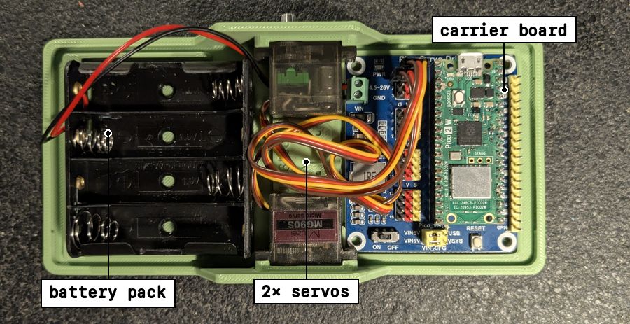
The plate's slots hold the board, both servos, and the battery pack by shape, no tape needed for any of it. Here's the whole thing seated, before legs go on:
4A · Carrier board into the plate
Seat the board into its slot at the top of the plate, header pins up. It should sit flush and not rock.
4B · Servos into the plate
Press both servos into their side slots, shafts pointing out to each side. They push in, no screws needed. A dot of glue or a small screw can secure them further if you want, but it's not required.
4C · Battery pack to the board
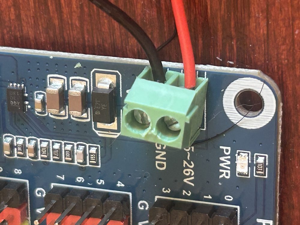
- red wire → the board's + / VIN power input
- black wire → − / GND
Never wire servo or battery power to the Pico's own pins. The carrier board handles power.
4D · Plug in the two servos
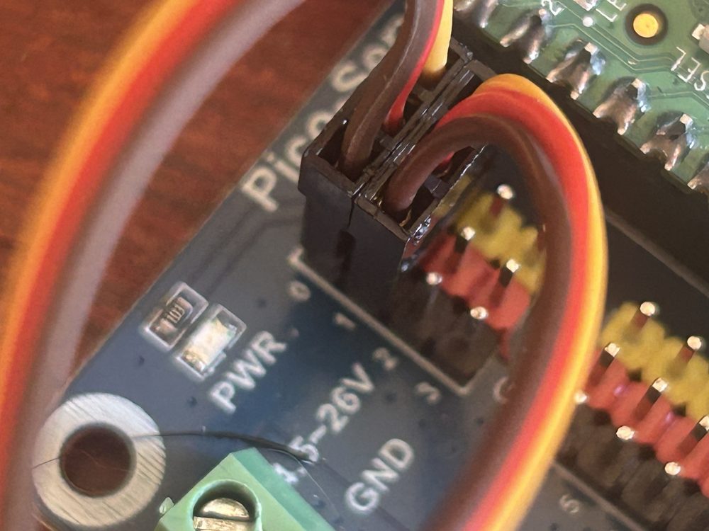
- left servo → the socket marked
0 - right servo → the socket marked
1 - every other socket stays empty
- each plug goes on as one 3-wire block, matching the board's printed order: orange/yellow/white = signal, red = power (the middle wire), brown/black = GND. If the colors don't line up with the labels, the plug is on backwards.
Trouble with this step?
My servo wires are different colors. Signal is the lightest (orange, yellow, or white), ground the darkest (brown or black). Follow the board's labels.
My board has 8+ servo ports. Use only the two named here. The rest are for other projects.
05First movement
Every power-up, the robot runs a leg check. The shafts are still bare, so watch the splined output shaft on top of each servo (the little post the horn will later clip onto): it rotates part of a turn each time, and you will hear the servo whir.
Every time you switch the carrier board on, it runs this calibration sequence first. Confirm the right servo moves first (you will confirm this again in step 07):
- 1 · CENTER, both to 90°
- 2 · RIGHT, right servo only
- 3 · LEFT, left servo only
- 4 · BOTH, both sweep together
- → HOLD at 90° for two seconds, then relax and join Wi-Fi
Trouble with this step?
Nothing moves. Board switch on? Fresh batteries? Servos only ever move on battery, never on USB alone. On a carrier board other than the Waveshare or the Kitronik 5329, the driver may be talking to the wrong pins: see want to use another board? in the parts list.
Only one moves. Reseat the still one's plug, and check it is in socket 0 or 1, no other socket does anything. Still dead? Swap the two servos between the sockets: if the fault moves with the servo it is the servo, if it stays put it is the socket.
They twitch and the board restarts. Weak power. Fresh lithium AAs, or a 5-6 V supply that can give 2 A.
A servo buzzes hard or runs hot. Power off, check the plug isn't shifted over by one pin.
06Attach legs to servos
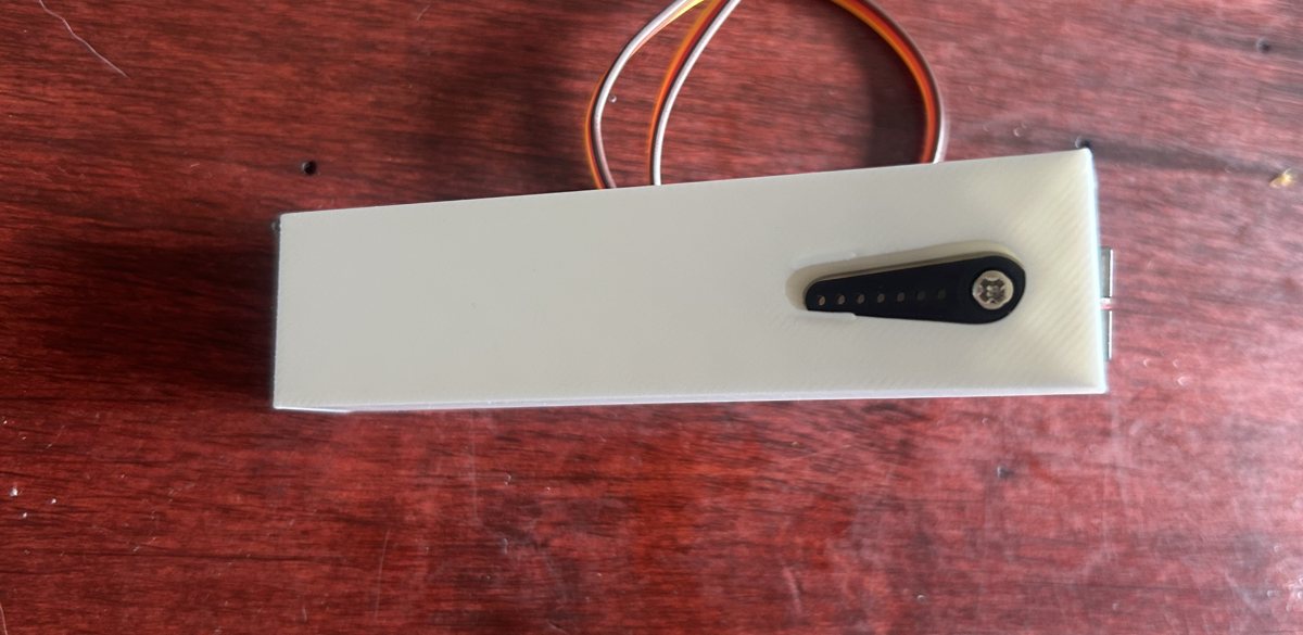
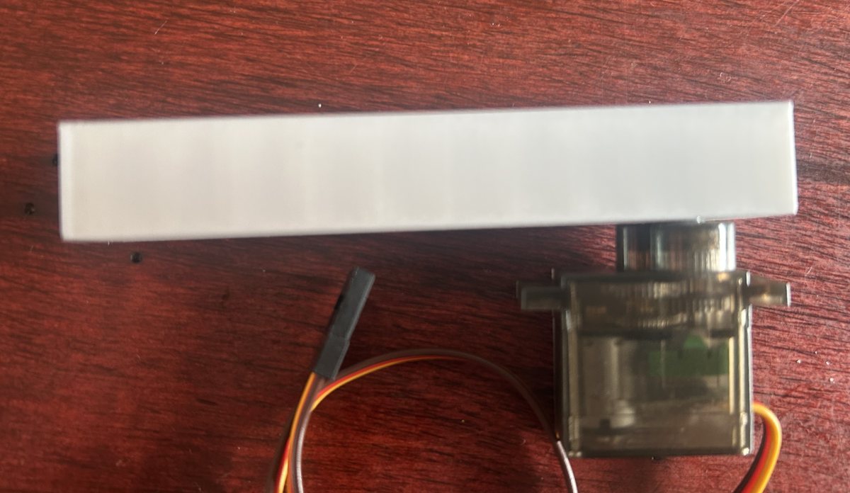
The trick: the boot check ends by parking both servos at 90°, so you can attach the legs after that.
- Power off, then power on and let the leg check run. Both servos end up parked at 90°.
- Attach each leg by dropping the horn into the slot, then screwing it onto the servo shaft so the leg sits perpendicular to the body.
Trouble with this step?
A leg sits crooked at rest. Pop it off the shaft, rotate it one tooth, re-seat on the next 90° hold.
The leg works loose. The small screw is not optional.
07Which leg is which
Legs are on, so now left and right can be settled for good. Power-cycle and watch the check again: both legs center together first, then the right leg swings on its own, then the left. That solo-right-before-solo-left is how you name the sides.
Reminder from step 04: it's the robot's own left and right, its left is your right when you face it.
Wrong leg first? Swap the two servo plugs on the board, and power-cycle to check again.
Then prove the phone can drive it: back to growbot.dev/tester, green dot, tap connect (wiggle test). The legs wave. In tab 1 · Calibrate, run Step 1 · which leg and confirm tapping left moves the left leg.
Trouble with this step?
Green dot but no wiggle. Board switch on? The board obeys only on battery power.
It was online in step 03, now it isn't. Power-cycle and give it 20 seconds. If it keeps dropping mid-play, that is usually weak batteries browning out the board.
08Mount the phone
The board, servos, and battery are already seated in the plate from step 04, and the legs are on. The one thing left: the phone.
- Foam-tape the phone to the front, centered and firm, camera at the top. Simplest way, and rubber bands work too. More mounting options coming soon, magnets included.
09It's built. Go meet it.
The body is done. Everything from here happens in the controller, on the phone riding the robot.
On the phone that rides the robot, not the one you have been reading this on. If they are different, type it in over there:
growbot.dev/tester
Work left to right through the tabs:
- 1 · Calibrate, teach it how its body is put together. Do this first, the walk depends on it.
- 2 · Move, its first steps. Wobbly is normal, that is the creature learning its own body.
- 3 · LLM, hand it a brain and watch it decide for itself.
- 5 · 🌱 Agent, let it off the leash. This is the one you built it for.
✓Checkpoints
| you did | which proved |
|---|---|
| phone check passed | the phone can be the brain |
| pairing code printed | board flashed, on Wi-Fi, has a name |
| green dot | phone ⇄ cloud ⇄ board all talk |
| both servos moved | power + wiring + ports correct |
| legs on at 90° | both legs start straight, so the walk begins from a known shape |
| right leg first, left means left | commands reach the right servo |
| body assembled | ready for the controller |
Anything on this list failing? Its step above has a "trouble with this step?" panel, and the 🤖 box at the top of the page knows this whole guide.